Disclaimer: This analysis is for educational purposes only. Modifying your e-scooter can be dangerous and may be illegal in your jurisdiction.

This article is a continuation of my series on scooter firmware security. Following my analysis of the Xiaomi 3 Lite and the more recent Xiaomi 4 Pro 2nd Gen, this post focuses on the Xiaomi Scooter Elite – a scooter made by yet another Chinese manufacturer called LEQI (Shenzhen LEQI Intelligent Technology Co., Ltd). For a general overview of the different manufacturers, see my guide to Xiaomi scooter models.
The goal of this research was to perform a firmware dump of the motor controller, analyze its architecture, and identify its security posture and behavioral logic.
Firmware Extraction
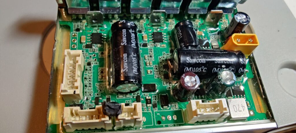
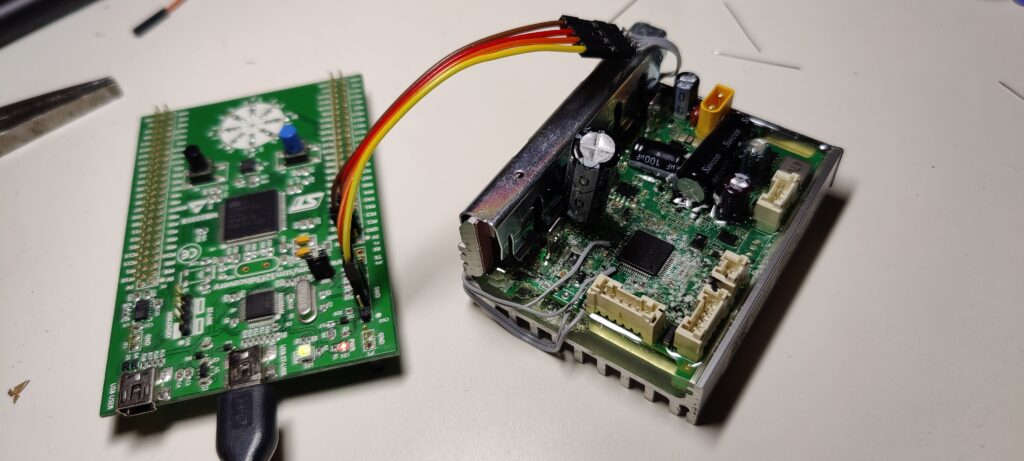
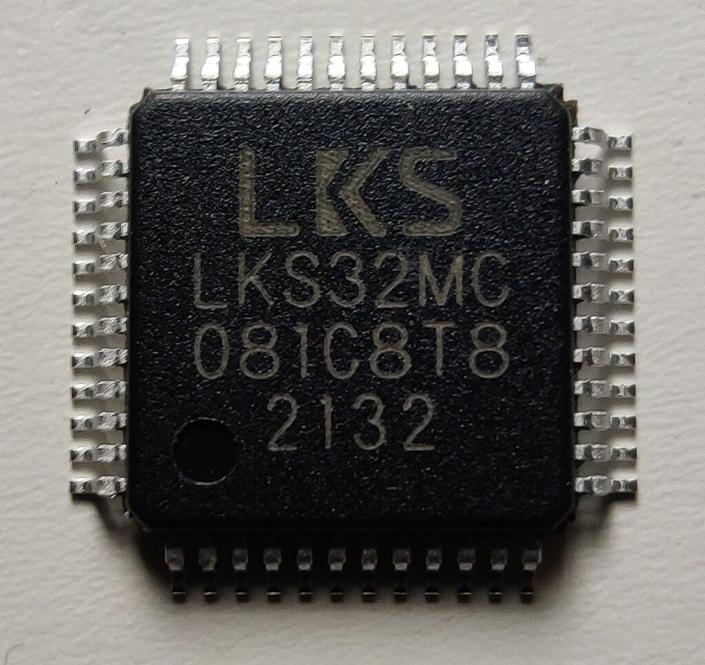
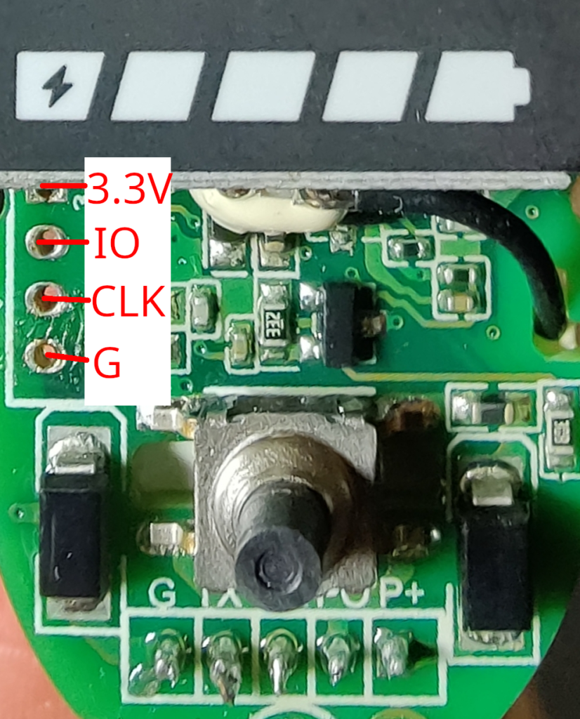
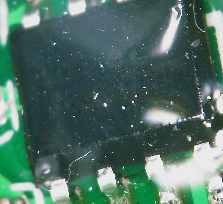
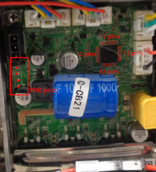
The motor controller is based on a Nations Technologies N32L406CBL7, an ARM Cortex-M0 clone. The initial analysis revealed that neither read nor write protection were enabled on the microcontroller unit (MCU). This is a significant finding, as it contrasts with the increased security measures observed on the Xiaomi 4 Pro.

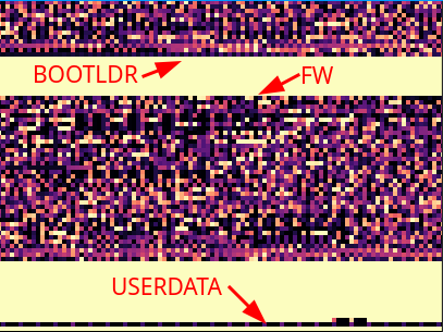
Consequently, a flash memory dump of the 128K flash was created without issue from the MCU’s flash memory using a standard SWD debugger. The flash contains the bootloader, ~48K of main application firmware and a small user-config section at the end.

System Architecture: Inverted Control
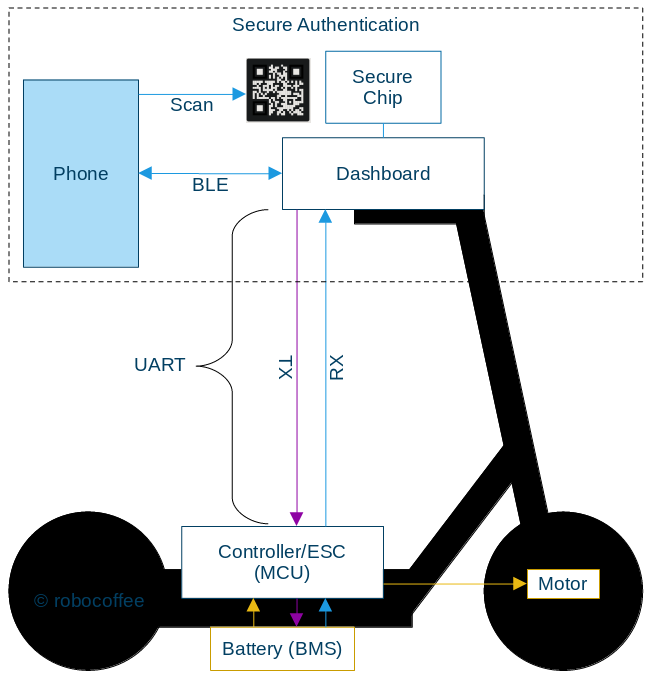
This LEQI scooter employs an inverted control architecture. In a typical scooter design, the motor controller is the system’s master, storing persistent configuration like the serial number and region settings in its own non-volatile memory. The dashboard serves as a simple user interface.
This scooter reverses that model:
- Dashboard: Stores and manages the scooter’s identity, including serial number and region code.
- Motor Controller: Operates as a stateless device, receiving its configuration from the dashboard via UART at every boot cycle.
This design makes the motor controller a modular, hot-swappable component, simplifying service and repairs. However, it also means the controller implicitly trusts all configuration data sent from the dashboard, as there is no authentication mechanism on the UART line. It introduces code redundancy due to low cohesion as responsibilities are scattered across components.

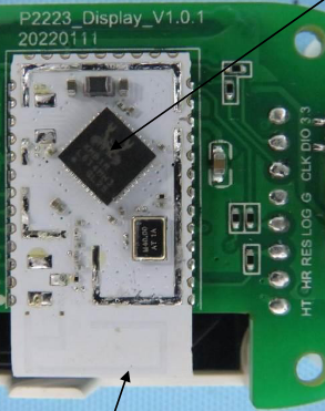
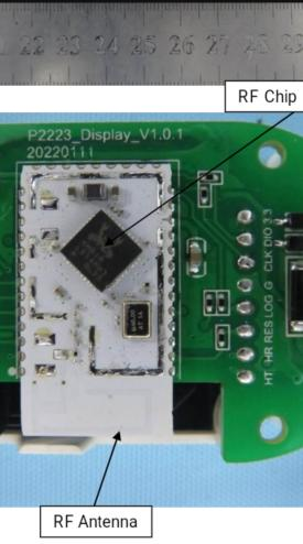
Further evidence for this architecture is found in the hardware itself: the dashboard’s BLE module is equipped with 512KB of flash, while the motor controller’s MCU only has 128KB (where not even half of it is usable by main firmware). This significant difference in storage capacity supports the finding that the dashboard handles the bulk of the configuration and “smart” features, while the motor controller is designed to be a more streamlined, motor control task-specific unit.
UART Protocol
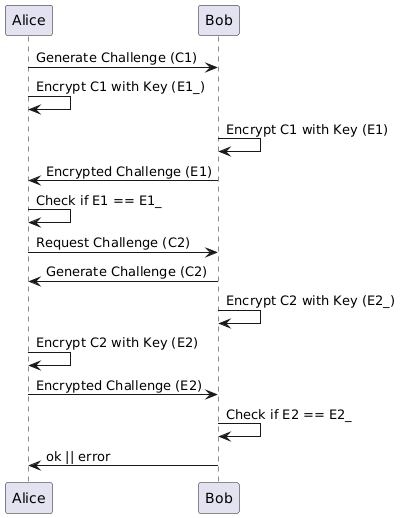
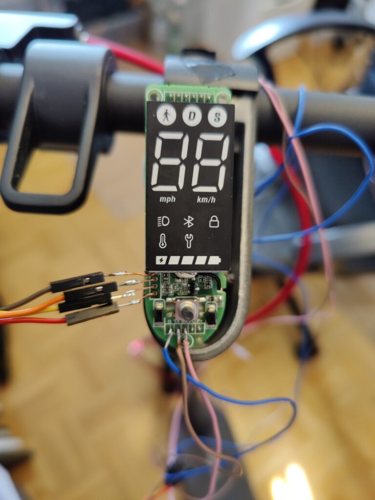
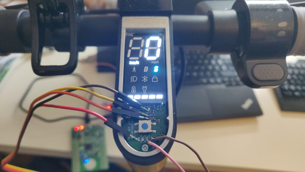
Communication between the dashboard and the motor controller occurs over a 5-wire UART interface at 19,200 baud. Analysis of the protocol revealed a standard packet structure (0x5A start byte, command, payload, CRC-16 checksum) with a notable design choice for handling responses.
Response packets use a nibble-swapped command byte. For example, a request with command 0x12 receives a response with command 0x21. This allows for efficient differentiation between requests and responses without additional state-tracking bytes.
The protocol also utilizes two distinct processing paths for commands, ensuring that time-critical motor control isn’t interrupted by configuration writes.
| Command | Path | Processing | Use Case |
|---|---|---|---|
0x12 | Immediate | Handled instantly in the UART interrupt. | High-priority data like throttle and brake updates. |
0x13 | Queued | Placed in a buffer for the main loop to process. | Less urgent configuration changes. |
Main UART Commands
While there are many commands, a few are critical to the scooter’s operation and provide insight into the system’s design.
| Command (Hex) | Direction | Handler | Purpose |
|---|---|---|---|
(0x12, 0x20) | Dashboard ↔︎ MCU | MCU | Real-time Control & Telemetry: Sent continuously (~30Hz) to provide throttle/brake inputs and request a status update (speed, battery, etc.). |
(0x12, 0x21) | Dashboard → MCU | MCU | Set Region: Sent on boot to configure the scooter’s behavioral mode (speed limits, throttle ramps) based on a 32-bit region code. |
(0x13, 0x23) | Dashboard → MCU | MCU | Motor Config: A queued command that updates motor enable flags and other operational parameters periodically. |
(0x12, 0x97) | Tool → Dashboard | BLE | Set Product Serial Number: Allows a factory tool to write the scooter’s 19-byte serial number, which influences region-locking and identity. |
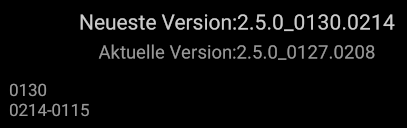
(0x12, 0x03) | Tool → Dashboard | BLE | Initiate Firmware Update: Puts the BLE module into firmware update mode, preparing it to receive a new firmware image for either itself or the MCU. |
Region-Based Behavioral Modes
The scooter’s operational parameters are determined by a region code sent from the dashboard. The firmware maps eight different region codes to five distinct behavioral modes, which alter speed limits, throttle response, and regenerative braking strength. The absence of a cruise control feature, likely due to the small 48KB firmware size, is notable.
| Mode | Region Code(s) | Max Speed | Throttle Ramp | Regen Braking |
|---|---|---|---|---|
| 1 (Standard) | 60544, 60546, 60547 | 22 km/h | Slow (Full power at 15 km/h) | 75% Strength |
| 1* (Unrestricted) | 60457 | 35 km/h | Slow (Full power at 15 km/h) | 75% Strength |
| 2 (Germany) | 60543, 61137 | 22 km/h | Fast (Full power at 7.5 km/h) | 100% Strength |
| 3 (Enhanced) | 60545 | 27 km/h | Fast (Full power at 7.5 km/h) | 100% Strength |
| 4 (Restricted) | 64020 | 22 km/h | Slow (with 65% multiplier) | 75% Strength |
For example, to comply with German regulations, the firmware not only limits the speed but also provides a more responsive throttle curve and stronger braking to compensate for the lack of other features.
Speed Limit Enforcement
Speed limiting on the Elite is not governed by a single static value, but is a dynamic process that combines a hard-coded regional cap with a variable limit sent from the dashboard.
- The Regional Hard Cap: When the scooter boots, the region code sent from the dashboard is used to set an absolute maximum speed in the controller’s memory (e.g., 22 km/h for Germany, 35 km/h for Unrestricted). This acts as a non-negotiable ceiling.
- The Dynamic Dashboard Limit: During operation, the dashboard continuously sends a “max speed” value in the real-time control command (
0x12, 0x20). This limit changes when the user switches modes (e.g., Pedestrian, Drive, Sport). - Firmware Derating & Final Calculation: The controller’s firmware takes the dynamic limit from the dashboard and may apply further reductions (deratings) based on environmental factors like battery level, motor temperature, and load. The final speed sent to the motor is the minimum of the regional hard cap and this newly calculated dynamic limit.
This layered approach explains a key quirk: if a user attempts to bypass the speed limit by only sending a high dynamic limit (e.g., 30 km/h) while the regional hard cap is still 22 km/h, the scooter will oscillate. It will accelerate towards 30, be cut off by the hard cap at 22, then repeat the cycle, never achieving a stable speed – a proper modification would require changing the regional hard cap first.
Inside the Control Loop: FOC, Calibration, and Safety
The controller’s firmware executes a Field-Oriented Control (FOC) loop at a brisk 20 kHz. Within each 50 µs cycle, it samples currents, runs Park/Clarke transforms, executes PI controllers, and updates the PWM duty cycles for the 3-phase motor output. This high-speed loop is also where the scooter’s user-facing ride characteristics are implemented.
Startup ADC Calibration
Before the motor can spin, the firmware runs an ADC offset calibration routine. It disables the motor outputs and samples all ADC channels 64 times to establish a zero-current baseline. This process compensates for hardware variations in the op-amps and current sensors, as well as temperature drift, ensuring accurate current readings during operation.
Kick-to-Start
A key safety feature is the kick-to-start mechanism, which prevents the motor from engaging from a standstill. The firmware uses a dual-check system centered around a 4.5 km/h threshold.
- Instantaneous Check: The main motor control function performs a simple, direct check: if the current speed is greater than 4.5 km/h, one of the conditions for motor engagement is met.
- Sustained Movement Check: For a more robust verification against false starts, a separate function analyzes the scooter’s movement over time. It smooths out noisy speed readings by averaging the last eight samples and only confirms a “kick” after seeing the averaged speed exceed the 4.5 km/h threshold for several consecutive readings.
To prevent the motor from rapidly cutting in and out if the speed hovers around the threshold, this sustained movement check also employs hysteresis. Once the motor is engaged via this method, the speed has to drop significantly lower (by about 2 km/h) before the motor disengages again, ensuring a smooth experience for the rider.
Throttle Ramping
Even after the kick-to-start speed is met, the controller doesn’t apply full power. Instead, it uses speed-based throttle ramping profiles that are also tied to the region mode. This creates the different “feel” between modes:
- Fast Ramp (Germany/Enhanced): Full throttle is available at just 7.5 km/h, making acceleration feel punchy and responsive.
- Slow Ramp (Standard/Restricted): Full throttle isn’t available until 15 km/h, resulting in a more gentle and conservative acceleration curve.

The “Emergency Brake” Flag
Previous scooters often included a “cruise control” feature to ride at a steady speed by holding the throttle in position for a set amount of time. In this firmware, that functionality is absent. Instead, FLAGS byte bit 5 of the main 0x12, 0x20 UART command acts as a motor disable or emergency brake. When this bit is set, the firmware immediately cuts power to the motor and engages strong regenerative braking, which can bring the scooter from 23 km/h to a stop in approximately 2 seconds. This is a critical safety feature, not a convenience one.
Firmware Security and Validation
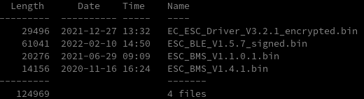
While the MCU itself is unprotected, the firmware update process has a two-stage validation mechanism designed to ensure integrity:
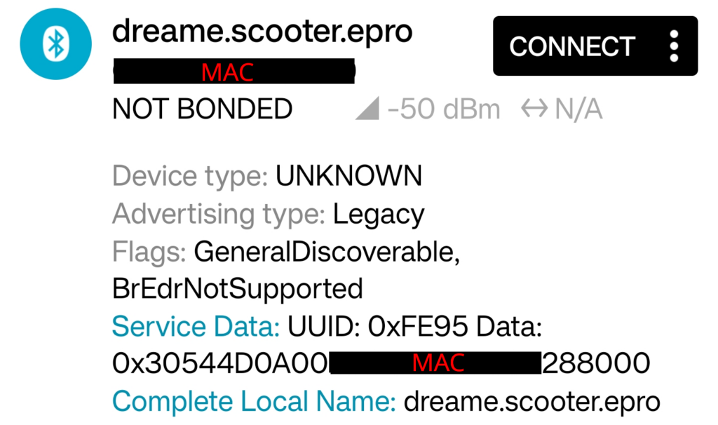
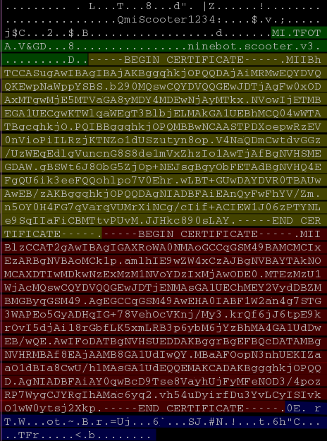
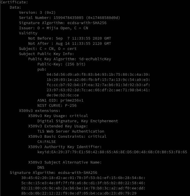
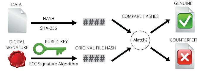
- BLE Firmware Validation: The dashboard, running on a Realtek RTL8762C, first validates any Over-the-Air (OTA) update package it receives from the Xiaomi app. It checks the package’s digital signature against a Mijia Root CA stored in its flash, ensuring the update is authentic.
- MCU Payload Validation: After the BLE module extracts and sends the raw firmware payload to the motor controller via UART, the MCU performs its own check. The firmware has an embedded CRC-16 checksum at the end of the encrypted binary. The MCU calculates a CRC over the received data and compares it to this embedded value before committing the new firmware to flash.
Notably, the MCU doesn’t use a standard CRC-16/XMODEM algorithm. It uses a custom implementation with polynomial 0x8005 (CRC-16/BUYPASS reversed) and applies bit-reversal to both the input bytes and the final 16-bit result. This use of a non-standard algorithm is a form of security through obscurity, effective at preventing trivial firmware modification without first reverse-engineering the specific CRC implementation.
Attack Surfaces
The architecture presents several vectors for modification:
- Dashboard Firmware Modification (Most Effective): Since the dashboard holds all the configuration logic, modifying its firmware is the most effective approach for persistent changes. The dashboard’s microcontroller also lacks read protection (write protection status is unconfirmed, as it was not tested), making this a highly viable vector.
- UART Man-in-the-Middle: A practical approach for temporary changes. An interposer device can intercept and modify the unencrypted region code command during the boot sequence.
- Controller Firmware Patching: This is another powerful vector. Since the MCU has no read or write protection, its firmware can be modified directly. A sophisticated patch could bypass the stateless nature of the controller by ignoring the configuration commands from the dashboard and instead implementing its own persistent logic (e.g., hard-coding a specific region mode or speed limit).
Conclusion
The Xiaomi Elite motor controller prioritizes serviceability and cost-effectiveness over a hardened security posture. The stateless nature of the controller, combined with the lack of read protection, makes it highly modifiable. Security efforts were focused on the BLE-enabled dashboard, which is the externally-facing component.
This architecture stands in contrast to the more locked-down approach seen in the Xiaomi 4 Pro, and is more aligned with the hackability of older models like the Xiaomi 3 Lite. The system is secure against casual, remote takeover but remains open to modification by users with hardware access.